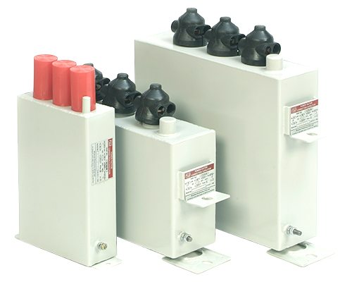
Oil Filled LT Capacitor
Manufacturing Characteristics of the Capacitor
The structure of the capacitor is composed of low power and low voltage MPP Film capacitive elements. The elements are connected in delta or star to reach the rated power and voltage.
These capacitors are designed keeping in view the harsh environment present in industrial sector. Metallized polypropylene film is used for the manufacturing of these capacitors which is known as the best technical and economical solution for low voltage power factor correction. Due to the self healing property and very low dielectric losses, high performance capacitors are designed.
Impregnating Oil:
It is a nontoxic, biodegradable, natural oil with a chlorine content < 5 ppm. Particular attention is given to the various phases of processing, to the oil impregnation of the dielectric and the drying process. The drying is carried out leaving the material for a long period in the autoclave under controlled environment, heating it to high temperature, where, at the end of the treatment, it reaches molecular vacuum. The treatment of the oil prior to use includes degassing and chemical depuration.
Case
The capacitor case is made of sturdy welded steel sheet which can withstand the normal stress produced by breakdowns. It is completely full and does not contain air bubbles: the prefect sealing of the container guarantees against deterioration of the materials, thus ensuring a long life for the capacitor.
The elasticity of the larger surfaces of the case compensates for the variations in the volume of the impregnating liquid in the range of temperatures during operations, thereby keeping the variations in the internal pressure to a minimum.
The container is also fitted with two handles to use for lifting and fixing the capacitor on the installation frame. Upon request capacitors destined for use in aggressive environments can be provided with a stainless steel container.
Terminals
The capacitors terminals are soldered on the porcelain bushings, glazed for perfect resistance to atmospheric elements. The porcelain bushings are metallized for both fastening to the capacitor cover and for fixing to the screw terminal connections. The bushings are perfectly sealed and particularly sturdy.
The screw terminals can withstand repeated torque stress of 20 Nm.
Flexible connections must always be used for electrical connections to the terminals.
Discharge Devices:
In conformity with standards the capacitors are internally fitted with discharge resistors for reducing the residual voltage to less than 50 V within 5 minutes of shutdown.
Environmental Compatibility of the Materials Used:
The impregnating agent used is the result of long and continuous research and experimental tests on all insulating oils for dielectric use currently available. It offers the best solution, taking into account the need to protect the environment along with the need to have high dielectric characteristics, the two requirements which have often been considered incompatible.
the impregnating agent is non toxic; its oral toxicity level (LD 50) is over 3 g/kg. Moreover, since these oils can be completely eliminated from human and animal bodies, there is no problem of accumulation.
The impregnating agent biodegrades rapidly in the environment, therefore, no special precautions are required to prevent the dispersion of oil into the ground in case of accidental leakage from the case.
It consists of the compounds of carbon, hydrogen and oxygen, the combustion of which produces carbon dioxide and water. These liquids are not considered dangerous and their registration is normally not required. However, the storage and destruction of the capacitors must be in accordance with current regulations in place of use.
Electrical Characteristics
| Nominal Rating | 2.5 kVAr up to 50 kVAr |
|---|---|
| Rated Voltage | 440 VAC (others on request) |
| Rated Frequency | 50 Hz (60 Hz on request) |
| Phase | 3 ph |
| Capacitance Tolerance | -5 % + 10 % |
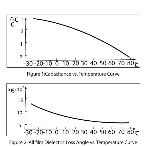
| Losses ( at Un 20°C after stabilizing) | All Film dielectric < 0.01 % ( < 0.1 W/kVAr) |
| Internal Discharge Device (Residual voltage) | 50 V after 5 min |
| Standards | IEC 831-1 |
Service Conditions
| Environment Conditions | Indoor Installation |
|---|---|
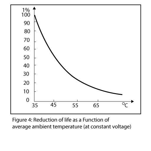
| Temperature Category (-25/C) | -25°C + 45°C |
| Temperature Category (-25/D) | on request |
| Maximum Altitude | 1000 m (a.s.l) |
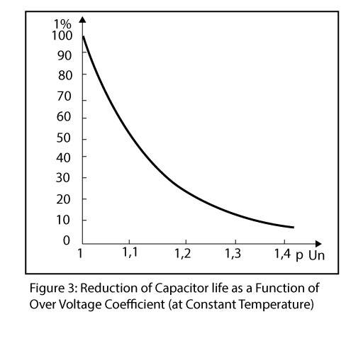
| Over Voltage allowed at rated frequency | 1.1 x Un |
| Switching Over Voltages | ≤ 2 √ 2 Un |
| Maximum Duration of Transient | 0.5 periods |
| Maximum Over Current Allowed for Simultaneous Presence of Over Voltage and Harmonics | I max ≤ 1.3 In (Per C = Cn) |
| Qn | Un | Cn | In | Dimensions | Part No: | |||||
|---|---|---|---|---|---|---|---|---|---|---|
| KVAR | KV | UF | A | a mm | b mm | c mm | d mm | Int. Connts. | ||
| Details | 2.5 | 440 | 41.1 | 3.28 | 260 | 320 | 6 | 8 | Δ | 1.0.F. 025. 440 |
| Details | 5 | 440 | 82.2 | 6.56 | 260 | 320 | 6 | 8 | Δ | 1.0.F. 050. 440 |
| Details | 7.5 | 440 | 123.3 | 9.84 | 260 | 320 | 6 | 8 | Δ | 1.0.F. 075. 440 |
| Details | 10 | 440 | 164.4 | 13.13 | 260 | 320 | 6 | 8 | Δ | 1.0.F. 100. 440 |
| Details | 12.5 | 440 | 205.5 | 16.14 | 260 | 320 | 6 | 8 | Δ | 1.0.F. 125. 440 |
| Details | 25 | 440 | 411.0 | 32.81 | 215 | 280 | 15 | 20 | Δ | 1.0.F. 250. 440 |
| Details | 50 | 440 | 822.0 | 65.63 | 315 | 380 | 15 | 20 | Δ | 1.0.F. 500. 440 |
Reference Standards and Tests
The capacitors in this series comply with the recommendations of the International Electrotechnical Commission IEC 831-1.
Routine Tests
- Capacitance Measurement
- Measurement of the tangent of the loss Angle
- Voltage test between terminals carried out at 4.3 Un in DC or at 2.15 Un in AC for 10 seconds
- Voltage dry test between terminals and container
- Internal discharge devices test
- Sealing test
Type Tests
- Measurement of the tangent of Loss Angle and capacitance at elevated temperature
- AC voltage test between terminals and container
- Lightning impulse withstand voltage test
Design Tests on Models During the Homologation of Types
- Short circuit discharge test
- Endurance test
- Over voltage test
- Overload run
Safety
There is a remote possibility of the capacitor exploding when it short circuits at the end of its life span, even though it has been protected in the best way possible. The situation is more probable with the three-phase capacitors in which the protection against short circuits require significant margins since it is necessary to protect against permanent and switching transitory overloads.
It is therefore necessary that the capacitors should always be segregated in a suitable environment in order to eliminate the risk of damage to people or things in case of an explosion.
Warning (High Voltage)
Products described in this catalogue can store lethal voltages, and energies. Utmost care should be exercised in the use of these products to assure that the voltage or power source is disconnected and the capacitors is discharged, grounded, and shorted before servicing the equipment where a capacitors has been installed.
Limited Warranty
KEL warrants its products under normal usage against any manufacturing defects for a period of one (1) year, from the date of delivery (also see warranty details).
Disclaimer
"The Capacitors described in this catalogue comply with national and international standards, such as IEC & IEEE. KEL disclaims all responsibility for damages of any kind caused by the utilization of its products in non compliance with these specifications".